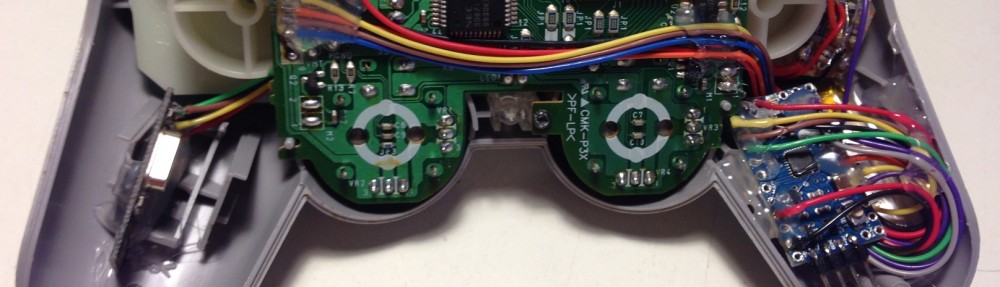
With some free time (and an unused GPS module) I decided to realize a GPS and temperature logger. It can be used for example to check if a good was moved through the right path and within a given temperature range.

In this project the microprocessor writes logging info into an external EEPROM to avoid directly removable parts (such as an SD card) that can be easily counterfeit. I have planned to write a full serial console program (over USB interface) to retrieve data and change board’s configuration, so no other hardware (except a computer and USB cable) is required.
Since I’m doing this board to experiment with interfacing and not to realize a market-ready product, I’ve also added:
- 3 blue LEDs
- an RGB LED
- 2 push buttons
- an expansion header
This board could be a nice starting point to learn how to interface and wire some devices, such as:
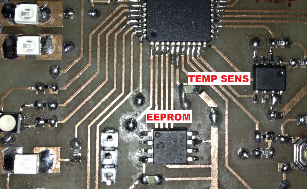
- a temperature sensor (Texas Instruments LM92)
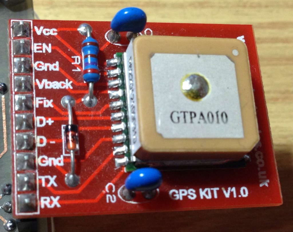
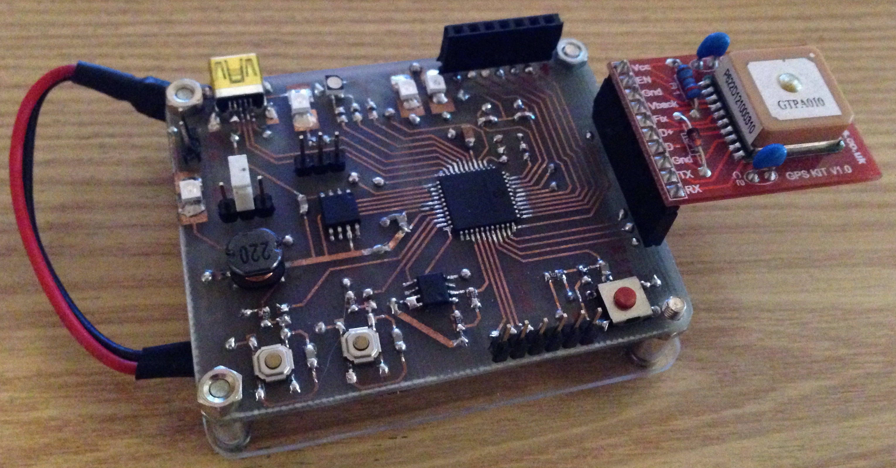
- a GPS module (GTPA010 – bought on eBay)
- an external EEPROM (Microchip 25AA1024)
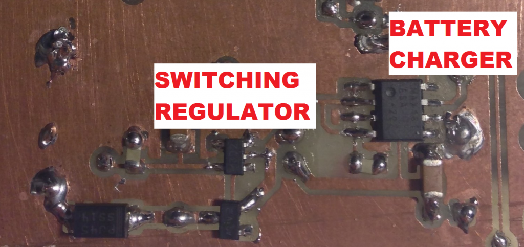
Some other chips are used to regulate supply and to recharge a LiPo battery (in my case recycled from an old Nokia phone):
- Microchip TC105 (switching drop-down regulator at fixed voltage)
- Maxim MAX1811 (USB 1-cell LiPo charger)
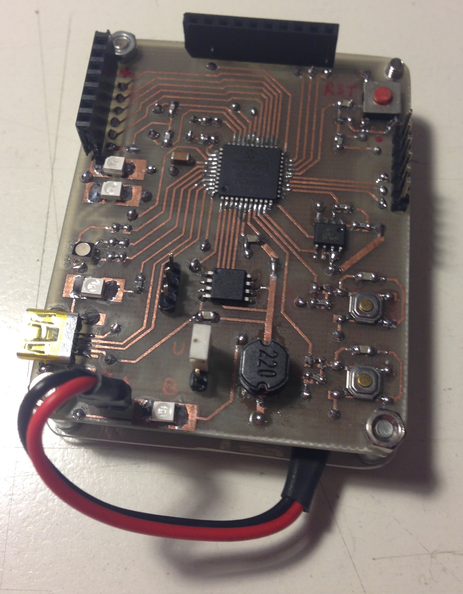
The board’s heart is an 8-bit Microchip PIC18F4553 microcontroller
| Program Memory (KB) | 32 |
| CPU Speed (MIPS) | 12 |
| RAM Bytes | 2,048 |
| Data EEPROM (bytes) | 256 |
| Digital Communication Peripherals | 1-UART, 1-A/E/USART, 1-SPI, 1-I2C1-MSSP(SPI/I2C) |
| Capture/Compare/PWM Peripherals | 1 CCP, 1 ECCP |
| Timers | 1 x 8-bit, 3 x 16-bit |
| ADC | 13 ch with 12-bit resolution |
| Comparators | 2 |
| USB (ch, speed, compliance) | Full Speed USB 2.0 |
| Operating Voltage Range (V) | 2 to 5.5 |
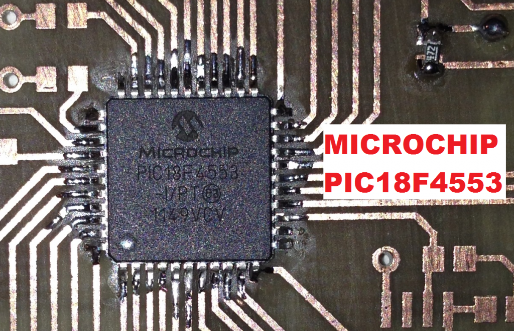
It is not as powerful as a 32bit processor but it can handle simple tasks (such as this kind of logging) with ease, moreover the ICSP programming header implemented on the board can provide power to the whole system, leading to a more flexible debugging.
Logged data is stored into a Microchip 25AA1024 serial EEPROM
| Density | 1024K bits (x8) |
| Operating Volt Range (V) | 1.8 to 5.5 |
| Max. Clock Freq. | 20 MHz |
| Page Size (bytes) | 256 |
It is connected to the main microprocessor through SPI protocol
Temperature is measured (and monitored) thanks to a Texas Instruments LM92 wired through I2C interface. This is an high accuracy (0.33°C) temperature sensor with integrated programmable alert.
The GPS module is a breakout board that I’ve bought on eBay for less than 20€ and is a GTPA010 (for datasheet just check on Google) based. It outputs NMEA strings via RS232 interface.
The power part is made by two integrated circuits and some external components. The Microchip TC105 is in charge to regulate 3.3V for the whole board, it requires an external P-MOS, an inductor and a fast diode. Instead, the Maxim MAX1811 is pretty ready out-of-the-box, and just need to be configured in current (500mA or 100mA) and in voltage (4.2V or 4.1V) according to battery’s need. For 3.7V Lipo should be used 4.2V (such as in my case). I’ve also chosen 500mA because the whole board is powered after the battery, so no more than the amperage provided by MAX1811 can be consumed (however a standard USB port doesn’t provide more that 0.5A).
This is the full schematic (created with CadSoft EAGLE)
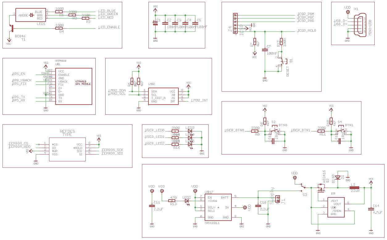
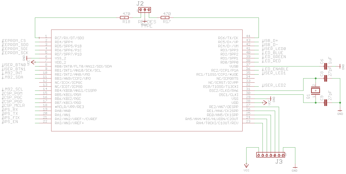
some parts (such as GPS module) are written by me.
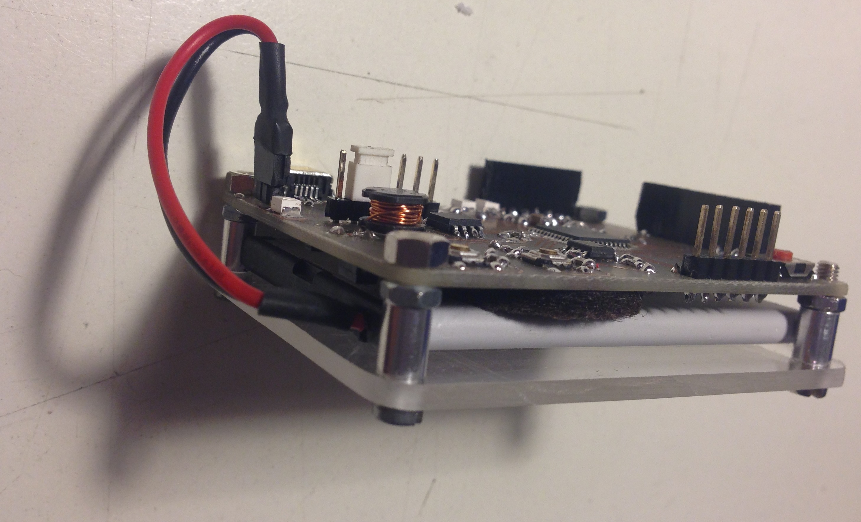
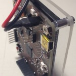
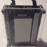
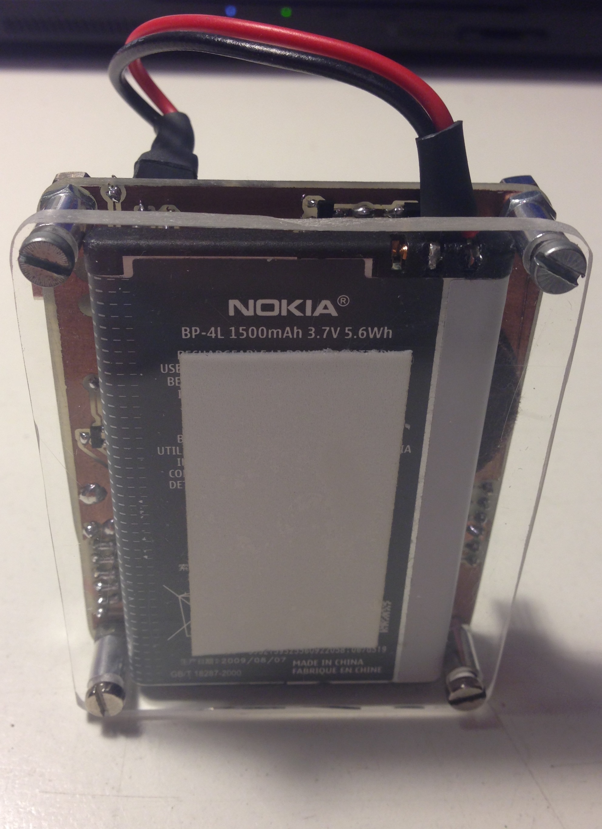
The final device looks like this
-
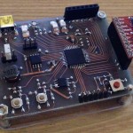
- above view
-
- front view
-
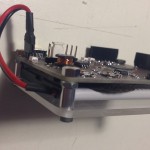
- side view
-
- side view
-
- bottom view
I’ve flashed the board with a really simple blinking example, no processing is made for the moment. If interested, check the video below
If you think this post can be helpful (for you or a friend), feel free to share!
Hello ;
I need the source Code LM92.
Can you help me ?
Thanks.
I’ve abandoned the project and I have not written the code for the temperature sensor, sorry