It’s time to write about a more complex but interesting connection with the STM32F4-Discovery board. Since I started developing with electronics, I’ve found a lot of applications in which an LCD is needed or can be an added value, specially if it includes a Touchscreen.
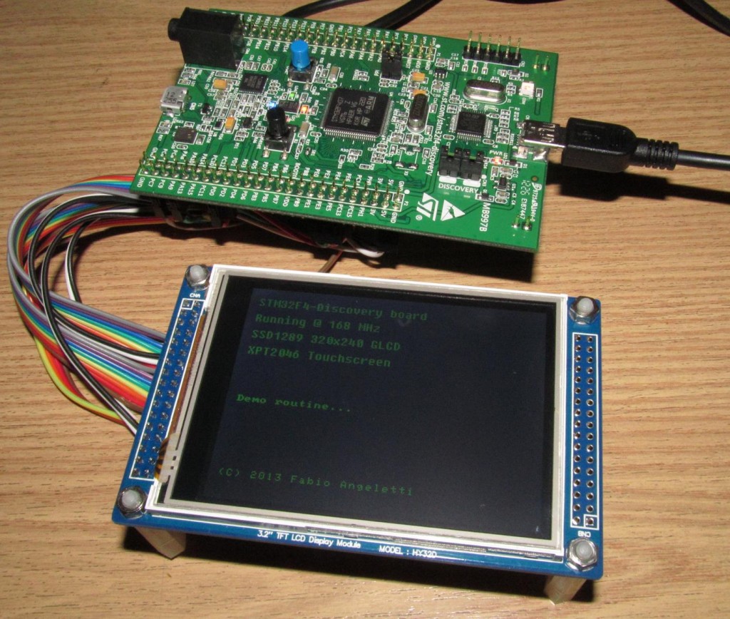
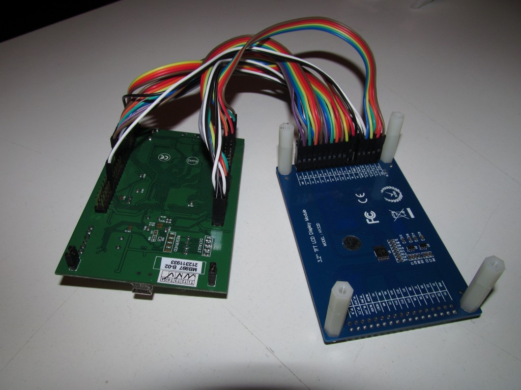
Last week I received a 3.2″ TFT LCD with Touchscreen from waveshare, model HY32D. It is based on SSD1289 display controller and also includes a touchscreen interface based on XPT2046 which communicates over SPI link. With a QVGA resolution (320×240 pixels) is enough for many applications and, more important, it is very affordable.
When working with new hardware, the most important thing is retrieving datasheets, to analyze protocols and understand how it works.
Well, fortunately Waveshare (LCD module supplier) includes some code to drive different kinds of displays and touchscreens. On Waveshare module’s page there is also a very helpful table that indicates the pinout (also the module itself has named pins on bottom side) that helps wiring to the board. Basically I have connected in this way:
| PIN NO. | SYMBOL | MODULE | STM32f4-discovery |
|---|---|---|---|
| 1 | 5V | 5V power supply | +5V |
| 2 | GND | Ground | GND |
| 3 | D0 | Data lines | GPIOE |
| 4 | D1 | ||
| 5 | D2 | ||
| 6 | D3 | ||
| 7 | D4 | ||
| 8 | D5 | ||
| 9 | D6 | ||
| 10 | D7 | ||
| 11 | D8 | ||
| 12 | D9 | ||
| 13 | D10 | ||
| 14 | D11 | ||
| 15 | D12 | ||
| 16 | D13 | ||
| 17 | D14 | ||
| 18 | D15 | ||
| 19 | CS | LCD chip select | GPIOD.14 |
| 20 | RS | Instruction/Data | GPIOD.15 |
| 21 | WR | Write | GPIOD.12 |
| 22 | RD | Read | GPIOD.13 |
| 23 | RESET | Reset the controller chip | GPIOD.11 |
| 24 | NC | Not connect | NC |
| 25 | BLVCC | 5V or 3.3V | +5V |
| 26 | BLGND | Ground | GND |
| 27 | BLCNT | Backlight brightness adjustment | GPIOA.0 |
| 28 | TP_IRQ | Touch screen interrupt | GPIOC.8 |
| 29 | TP_CS | Touch screen chip select | GPIOC.9 |
| 30 | TP_SCK | Touch screen SPI clock | GPIOC.10 |
| 31 | TP_SI | Touch screen data input | GPIOC.12 |
| 32 | TP_SO | Touch screen data output | GPIOC.11 |
| 33 | 3.3V | 3.3V power supply | NC |
| 34 | GND | Ground | GND |
The backlight control pin is attached to pin 0 of port A because this one can be used as PWM output with TIMER2 (although this function isn’t implemented yet). PWM enables an adjustable backlight system that could be useful in some applications.
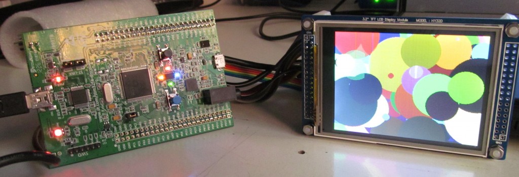
Everything works as expected, there is a demo video
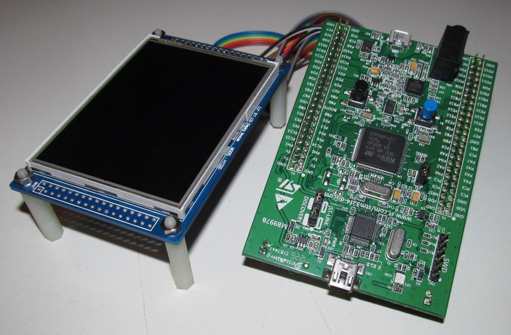
More images
The complete source code is here: stm32f4_lcd_touch
If you think this post can be helpful (for you or a friend), feel free to share!
HI, can i know which software your used to design the screens and can u please tell me which compiler was the best for this
The ASCII art turtle was made using an BMP-to-ASCII converter software, I don’t remember the application’s name but I’m sure you can find one searching for “image to ascii converter” on google.
Speaking about compilers, there isn’t an absolute winner in all fields, depends on the optimization you are looking for (code size, speed, etc.). I personally use Keil right now, but sooner I’ll switch to GNU-ARM because I like the opensource. However if you are in doubt, check here, it is a very well-made comparison of ARM compilers.
More recent ARM compiler comparison:
http://www.silabs.com/Support Documents/TechnicalDocs/AN720.pdf
Dear Fabio
i’m very interesting about your GLCD’s source code, I’ve just bought a same TFT like yours. But can I have a question about the draw_picture function ?. The picture is a 16 bit array, isn’t it ?. If it is, is there any application to convert image to array file header.
Thanks so much and best regard.
Have a nice day 🙂
I used “Embedded Resource Editor GUI” from ST site.
Open the program then click on “Tools -> Image 565 Converter”, select the image and click convert.
hello, how can i open this project with Keil uVision ?
Thank
Hello and thank you for interest.
On Keil uVision you have to create a project according to your hardware and then add the source code files to the project. If you need help creating a project, you can follow my tutorial HERE
What pins do you connect to for the data lines. I see you mention GPIOE, so I am assuming the D0 is connected to PE0, D1 -> PE1, etc. Is this assumption correct?
Exactly as you said, D0 is connect to PE0, D1 to PE1, and so on.
Can you re up the xpt2046.pdf, the link was died. That note is the user manual or just the datasheet ???. I do not understand too much about how the xpt2046’s chip working, can u please explain to me, especially the coordinate’s calibrate
Thanks for notification, I’ve update the link. However it only refers to the datasheet, procedures like calibration must be implemented by the user but in the source code there is a calibration routine that you can check if needed
HI You! I use LCD 2.4in have resolution (240×320 pixels), How can I fix this Code?
Different resolutions aren’t currently fully supported. Try to check if the controller (SSD1289) has some configuration register to modify, then check if some routine has to be fixed
Hello, I’m having trouble when reading touch coordinates. I’m using Read_XPT2046() command and it always give 8048,0 . why? ( XPT2046_Press command is working)
Have you used calibration routine before?
yes! here is my code for reading coordinates:
Coordinate *cord;
if(!XPT2046_Press())
{
cord=Read_XPT2046();
PrintNumber(cord->x);
PrintNumber(cord->y);
}
before using, you have to initialize the coordination matrix using the function TouchPanel_Calibrate()
my fault!, now it works!
another problem, How to save calibration matrix? (data type is long double)
Hi ! I touched but after touch 3 times , it stopped and I can’t touch continue? why ?
IT’s stopped at “setCalibrationMatrix(&DisplaySample[0],&ScreenSample[0],&matrix );”
Can You helpe me slove this problem ?
It’s a strange behaviour, what have you changed in your application?
Hello,
I am working on a project where i have to use a 3.2″ TFT LCD. I bought a TFT LCD
Model # HY32D
LCD Controller # SSD1289
I came to your blog and saw your work. So, I took your code and tried to use it in my project .
I am using a PIC24FJ128GA010 microcontroller. I chnages the I/o definitions of your code to work on my PIC.
But it is not working. The LCD is not responding to anything.
After all that i started reading the SSD1289 datasheet and saw the timing diagrams of the read write signals. They seem all ok as you have also posted the video here (Thast everything works).
I need help in finding out if my LCD is dead or what is the problem.
Thanks
I’ve not used this LCD module with a microchip device before, however try to check your SPI configuration and connections. If you can give me other details maybe I can help
Hi ! What program you use to convert fonts ? I want to convert another fonts . Thanks for help 😀
hi!
i don’t speak English, but i like your project!
can your help me?
You share to me! My project ! I don’t know about driver Controller SSD1289!
vui lòng giải thích cho tôi về các lệnh của SSD1289!
Thanks for all!
I’m sorry, I have not understood what are you asking
Hi Fabio Angeletti,
First of all, thank for your sharing projects and could you tell me how can you genarate font library in ascii lib. I would like to use another font size. Thanks very much.
Hi, and thanks for interest! The whole library was made by a python script. Unfortunately I have lost the script during my last computer failure. However the script reads the font, generate bitmap of wanted size for each character and than parses this bitmap to create the array.
Hi.First of all,Thanks for sharing.I have a question.I am working on Gui applications.You got any codes?İf it is,please share….
I don’t use GUI applications at the moment. Try to check if there is something on the ST’s site, I’m pretty sure they released a library or some application.
hi thank u for all of this tutorial
i just want to ask how i can know if my lcd is defective??
sorry for the very late reply. troubleshooting and testing a component can be a very difficult process. try to start with a complete and working project, create it with no change and test if everything works as expected. after this step you’ll know if the component is working, instead if this step fails, check connections (often these are defective). take in mind that the majority of discrete electronics components are created in batch so is not impossible that something went wrong and so you are handling a defective part. feel free to contact me for additional help and tips
Thank you for your participation in helping me, I used STM32F429 and everything works perfectly (with a low price and a gain of time)
Hi!
Is it possible for you guys to upload a fully working projekt file for
Keil or Coocox ?
regards Michael
I don’t use CooCox, for Keil you can start from my guide on this blog. however by the very high interest, I’ll upload full working projects in the next articles, please keep patience for the moment because I am really busy these days
I have a waveshare tft 3.2 just like this one:
http://www.wvshare.com/product/3.2inch-RPi-LCD-B.htm
So i think its the same you talk about, im going nuts trying to find a way to turn off the backlight in the tft?
Not at all, the exact model of my display is HY32D. However if the LCD’s controller is the same, yes, you can use my code just wiring it accordingly. From the website that you have linked I don’t see any backlight pin that permits the hardware control on the light. If you have a datasheet (that I don’t see) check for an SPI command
Do you know how to use the LTDC of the STM32F4 to interface to a RGB interface TFT ?.. any example ?
I’m still waiting to receive the new STM32F429 discovery board. For the standard STM32F4-Discovery (that I use) I don’t think there is an LTDC peripheral integrated 🙁
I have problems with touchscreen, i use Read_XPT2046() command and it give me 1 result, i use the function TouchPanel_Calibrate() before, thanks you !!!
TouchPanel_Calibrate() works as long as the function Read_XPT2046() returns a value. Try to check all connections between the LCD and the board. Have you changed anything from the code or implemented other functions that can affect its behaviour?
while(1){
if(!XPT2046_Press())
{
cord=Read_XPT2046();
SSD1289_Clear(Black);
SSD1289_CleanTextFont(cord->x, cord->y, “Hello, World!”, Red,16);
}
}
I added this code to main.c, but it not work, the text not move when touch any where ?? I checked all connection it’s ok and i don’t change anything in your source code !
Read_XPT2046() doesn’t return the exact position as XY pixels on the screen. Add this function to XPT2046.c (and the prototype in XPT2046.h):
void getExactPoint(int *x, int *y)
{
Coordinate screen;
getDisplayPoint(&screen, Read_XPT2046(), &matrix);
*x = screen.x;
*y = screen.y;
}
and everything should work correctly.
Please let me know
I forgot it !! now it work ! Thanks you very much ! , Ah how the command TouchPanel_Calibrate() work ?
I readed this WORK and used some help from the display manufacturer (that provided me some code)
while(1){
if(!XPT2046_Press())
{
cord=Read_XPT2046();
SSD1289_Clear(Black);
SSD1289_CleanTextFont(cord->x, cord->y, “Hello, World!”, Red,16);
}
}
I added this code to main.c, but it not work, the text not move when touch any where ?? I checked all connection it’s ok and i don’t change anything in your source code !
My program crashes after setCalibrationMatrix (& DisplaySample [0], & ScreenSample [0], & matrix);
Can you provide me more infos? Which compiler are you using? I haven’t experienced this kind of behavior in my tests
Thank you for replaying.I have Open Cortex-M4 Kits Open407V-D, and I use keil uvision. I try to do an application resembling as proposed in this web site page. At the first part the LCD work correctly. But in the second part I have a problem when I want calibrate the screen touch. When I add the line “TouchPanel_Calibrate();” in my program , the card blocked in the third square of calibration. After many operation ,I look that the problem is related with this line “setCalibrationMatrix( &DisplaySample[0],&ScreenSample[0],&matrix );” located in “TouchPanel_Calibrate()” function in xpt2046 library. When I remove this line the card work and he run correctly, but the Touchscreen is not calibrated.
I’m pretty sure your problem is related to the handling of long double type in the matrix calculation. Open XPT2046.h and change the matrix typedef’s type from “long double” to “int”. Please let me know
Tank you a lot, the program work correctly. Please can you explain me why « long double” was cause a problem ?
I’m not sure about it, initially I used this type to obtain the maximum possible precision during calibration phase (and it worked fine, since it is exactly the same code as the demo video). Now, after you advice, I tried with the int type and it works correctly (no precision issues). To answer your question, I don’t know why there is such kind of problem with long double types, on my environment it works. However to avoid future issues I’ll use int type too since it is surely faster and precision on the touchscreen is still good
I want to display a photo in the LCD. Please can you have an idea to how can I proceed ?
You have to convert the photo in bitmap (with correct dimensions), transform it to a binary C file and then draw it on the display with the function LCD_DrawPicture or LCD_DrawPicture8bit depending on the encoding of the C file. This solution uses a LOT of memory. Another approach is load it on an SD-Card and then draw from there but is a more complex process. I can’t be more precise at the moment cause I’m really busy, soon I’ll write a tutorial about this
Thank you and take your time
Please, help me. i have a stm32discovery with stm32f407vgt6 and this it work at 3vcc……i was programed gpios at 100mhz. so i have a problem with lcd tft 3.2″(ssd1289). the lcd work at 3v???? is fast gpio 100mhz for lcd?in my code do not use delay for sending command to lcd……help =)
[email protected]
The speed is more than enough, try to slow it down but I’m pretty sure that the problem is not here. SSD1289 supports 3V signals, don’t worry about it
Hi, I want to compile the code but there is one file “stm32f4_discovery.h” you did not provide in your code package.
Could you please email me the file?
I am in a hurry, Thank you very much.
I’m sure I’m late, sorry. However I used the old version of the Standard Peripheral Libraries that are no longer supported for this project. I suggest to try switching to the newly and long term HAL libraries. A similar file is called “stm32f401_discovery.h” and it is inside the support package for STM32F4 that actually you can download from the STM32CubeMX application. It will be saved by default in C:\Users\YOURNAME\STM32Cube\Repository\STM32Cube_FW_F4_VX.X.X\Drivers\BSP\STM32F401-Discovery.
Hi, there is a file missing in your code package.
stm32f4_dicovery.h
could you please send me the file ?
I cannot compile without this file
Thank you very much
See previous response
I can not get the exact point. (I used your getExactPoint() function.) can you help me pls??
Can you be more specific?
Nice explanation. Thanks.
I’m using LCD with ILI9341 LCD Driver and XPT2046 as touch interface. Here is it’s link: http://www.buydisplay.com/default/2-8-inch-tft-touch-shield-for-arduino-w-capacitive-touch-screen-module
It contains common SPI for both TouchScreen as well as LCD.
While using your xpt2046.c and xpt2046.h my code sucks at below in Calibrate function:
do
{
ILI9341_CS_RESET;
Ptr = Read_XPT2046();
}
while( Ptr == (void*)0 );
Ptr returns always 0.
Can you help in solving the same ?
Thank You! 🙂
I’m new with this display so I’m not sure I can effectively help. Have you tried to interface only the touchscreen without talking to the LCD? It should be useful to understand where is the problem.
Hello,
Did you succeed with your project, can you share it?
Thanks
The project is working but I have not the full project right night, since I change the whole environment. I’ll try to update everything as soon as possible, maybe I’ll migrate to Github
The project is working but I have not the full project right now, since I change the whole environment. I’ll try to update everything as soon as possible, maybe I’ll migrate to Github
Hi,
Firts of all i admire you work … good job ^^, and actually i’am getting started with the STM32F4-Discovery board for TFT LCD application and a would to know what SPI interface are using ? 4-wire 8-bit or 3-wire 9-bit ?
Thank you
The LCD controller uses no SPI interface, it is a parallel one. The SPI used by this panel is only for the touchscreen sensing
My display does not use a SPI interface, is more like a parallel one. However, you can use my routines with another display that uses, instead, a SPI interface. The vast majority, however, uses 4-wire 8-bit
Hi! Thanks for this nice explanation.
I’m using your code to run my LCD having ILI9341 driver using SPI4 and XPT2046 driver for touch using SPI2. Modified your code accordingly.
I’m getting all the time the values of m1,m2,m3 = 0 and get 0 after converting integer of getExactPoint() to string.
Can you help?
Thanks
Are you using exactly my code other than the small modifications needed in your application?
Hi
if you need example project for ili9325 (waveshare) on STM Cube HAL
I will give [email protected]
I’m evaluating some displays right now and one of them has an ILI9325 controller. Thank you very much for sharing!
Hello Fabio!
I have recently bought the same LCD as yours and I haven’t started using it yet. Then I saw your excellent page! WoW, your work is amazing.
I would very much appreciate if you can answer me a question. You are connecting PIN 27 (BLCNT) to a pin in your MCP that generates PWM by software right?? In other words, this LCD pin needs a PWM signal??
Also, is there any difference if I connect pin 25 BLVCC to 5V or 3.3 V??
Thanks a thousand for your helpful advice.
Kansai
Hi! It is me again.
I ve noticed that my LCD is an updated version of yours. Its controller has changed, now it is the ILI9325. However, apart from some registers that have changed , they are quite similar.
I ve programmed it for a PIC18F micro (only the LCD part yet) and it works great except the LCD_Clear() function (what in your program is the SSD1289_Clear()). This only clears a small fraction of the screen.
I ve noticed that all functions use a Write Index, Write Data pattern but only Clear function use a Write Index then multiple Write Data functions. I wonder if the error could be related to that. Any advice will be greatly appreciated
Hello again
I solved the last thing I posted. In the code, I changed a line to cast the product as a long integer, because otherwise the clear function does not work.
I am now trying the touch panel functions and it does not work (>>=3; instead of buf>>=4; ???
I mean, only 12 bits are being used (as you can see in buf&=0xfff;) so if the bits are shifted only 3 positions, a bit is lost, isnt it??
I don’t remember exactly why I used such statement but, of course, your deduction is correct. If I have an uint16_t like 1000100110101011, and I shift it by 3, I obtain 0001000100110101. Then, with the AND mask 0xfff, I obtain 0000000100110101. I should check the datasheet and analyze the signals through an oscilloscope, but unfortunately I’ve not the hardware with me. I can assure you that the code was working, and other people used it successfully. I suggest to check the datasheet of both the STM32F407 and your PIC18F for differences in SPI implementation. Let me know when you’ll solve this issue!
Thank you for the reply. I ll let you know when I solve the issue.
One more question. How about the timing of the CLK of the SPI you used? Right now I am sending but got no reply from the XP2046. The freq I am using for the CLK is 1MHz I think. Maybe it is too fast?? I wait 1ms between control word and replies (from the ADC) but got nothing.
I think I have solved the issue. First, your code is right, but the datasheet is wrong. (they dont agree).
The problem was not timing. It was selecting the SPI mode. The datasheet seems to select Mode 1 or 2. Your code select Mode 0, and I used Mode 3. With Mode 0 or 3 it works.
Second, the X and Y commands are opposite. In your code X is 0x90 and Y is 0xD0 but in the datasheet is the opposite. Curiosly in the code of other people in the internet, it is like the datasheet. Perhaps your LCD and my LCD are special??
About the shifting, I think >>3 is ok because the response is late 1 cycle so it actually only has 3 0s inserted and not 4 as I thought.
Will try my findings tomorrow 🙂
I could imagine that the axis depends on the orientation of the display itself. If I’m not wrong, it is possible to select the orientation through software commands, such that it can be 320×240 or 240×320. Let me know if you find something interesting, I really like play with LCDs and currently I’m wondering about implement a 800×600 parallel LCD controller with an FPGA (I wish I have enough time!)
Hello.
My display is working fine so far. I solved all the issues…
I am wondering , have you investigated into how to display more complex GUI (buttons, sliders, etc) for this display? Even if you haven’t done it, have you heard about some resources for this??
Thanks
You should take a look in STemWin software package supported by ST Microelectronics and Segger. Check into the ST website for more info, I’ve used also for a project in this blog, the photo frame made with the STM32F7-Discovery board
Hi Fabio,
short question. I’m searching a Library for XPT2046 controller to us it with Arduino.
I bourght a 2.8″ TFT touchscreen from Waveshare but WS provides a very very simple Lib. I’m not the greatest C++ programmer of the world. During my search I found your Blog, but I’m not sure your Lib STM work with Arduino.
Do you have any ideas? My problem is to get coordinates from touch panel.
Sorry for my poor english.
It would be great you have some tips. Thank you very much in advance
Greets from Germany
Guido
Hi Guido! My library is optimized for use with ST MCUs. However, you can study just a bit the logic and replicate the control scheme to fit your application. The XPT2046’s datasheet surely will be useful. Pay attention to the calibration routine, since it requires also the control of a display (to plot crosses and text). The calibration, however, is not mandatory to be executed in real-time. You can calibrate the touchscreen and then save the configuration. Hope it helped!
Hello.
I searched but couldnt find your 2.8” from Waveshare. But since you said that it uses XPT2046…I wonder why do you say that they provide a too simple library. The one I got is not simple at all, I mean works quite great. You just have to port it to Arduino (you have to be very careful because it produces overflows quite easily in the integer calculations though)
If you are searching for touch libraries for arduino there is UTouch (companion of UTFT). However I must warn you that first it didnt work for me (it works for other people though) and second I find it quite inferior to the one of waveshare. .
Right now I have written a touch library based on waveshare code for mbed (STM32) and fo PIC18.. I was thinking of writing it for arduino too but it will depend of the few time I have
i have STM32F429i_DISCO and i have a problem with calibration
Hello, can I have more info? I don’t know how you have made the porting of the driver
Hi Fabio
I use stm32f407VG Discovery board , HY32D Display module , Keil 4.50.0.0 version and Windows 8.1.
When i try compiling project i am recive the error msg. “user\SSD1289.c(139): warning: #223-D: function “Delay” declared implicitly”
and
linking…
tesst.axf: Error: L6218E: Undefined symbol SystemInit (referred from startup_stm32f4xx.o).
tesst.axf: Error: L6218E: Undefined symbol STM_EVAL_LEDInit (referred from main.o).
tesst.axf: Error: L6218E: Undefined symbol STM_EVAL_LEDOn (referred from main.o).
tesst.axf: Error: L6218E: Undefined symbol SystemCoreClock (referred from main.o).
tesst.axf: Error: L6218E: Undefined symbol TouchPanel_Calibrate (referred from main.o).
tesst.axf: Error: L6218E: Undefined symbol XPT2046_Init (referred from main.o).
tesst.axf: Error: L6218E: Undefined symbol XPT2046_Press (referred from main.o).
Target not created
can you help me ? or maybe upload your full project .Thank you so much!
I don’t have the full project right now. However, the problem can be resolved including the required files in you environment. Check the included files and also the required .h files.
hi
thank you for your source code. but it is not working in my project.
can i have main.c ?! plz
hello !
I’m looking for a way to make the LCD display with out TFT controller.
So, very interested your program & Code & video.
i have some question.
first, if i use your program source, make the LCD program? without external TFT controller.
Seccond, if i can’t, (that means, like your LCD Display)
what IC i need to develop a program?
The LCD program is composed by two parts: the driver for the SSD1289 controller (embedded in my LCD) and a graphical library that is easily portable. In which parte are you exactly interested into?
thanks for this one it helps me a lot, one thing i have to ask is my lcd touch module is with ili9341 controller so some pins related to back light is not there in module and i am using stm32f407vgt discovery board so what will the changes in my case.
I’m not sure I have understood what you need. You have a LCD with the ILI9341 controller but not all PINs are accessible?
nice job ! The code works without any changes also on the STM32F207.
Thanks for sharing your work !