The Schumann resonances (SR) are a set of spectrum peaks in the extremely low frequency (ELF) portion of the Earth‘s electromagnetic field spectrum. Schumann resonances are global electromagnetic resonances, excited by lightning discharges in the cavity formed by the Earth’s surface and the ionosphere.
(from Wikipedia http://en.wikipedia.org/wiki/Schumann_resonances)
Schumann resonances are claimed to provide equilibrium between people and Earth, since the main frequency (7.83Hz) has a wavelength of 38000Km (about the circumference of the Earth). Most of scientific community argued that a body small like the human one can’t obtain advantages from this frequency. Despite of this, some audiophiles (in which I also agree) says that when in presence of a Schumann resonance the music listening is more relaxed.
The project is made of 4 parts:
- A power supply adapter
- A simple NE555 based oscillator
- A small power transistor to drive the antenna
- An antenna suitable for this purpose
The schematic is pretty simple
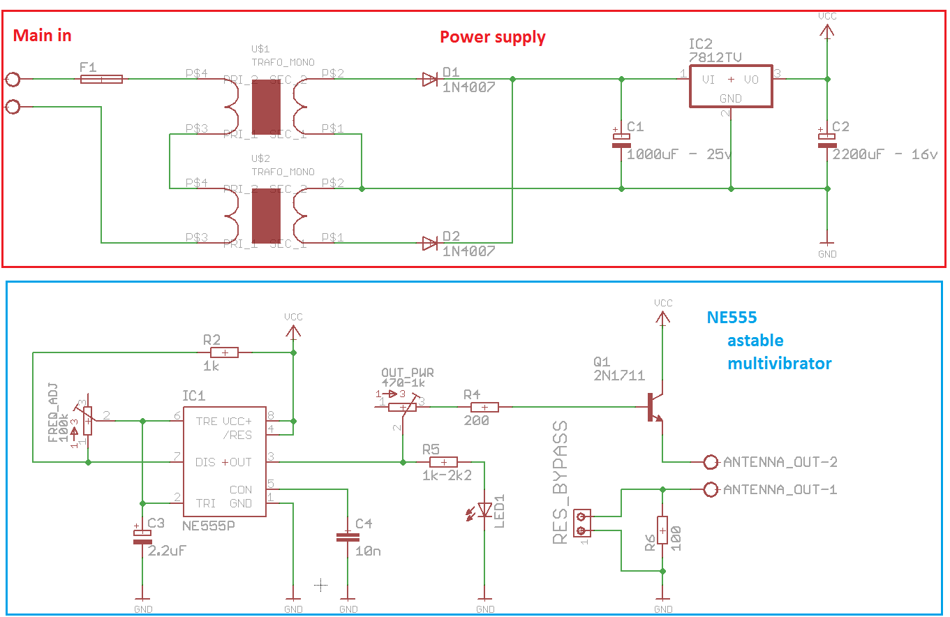
The NE555 is probably the most known integrated circuit in the story. It can be used to generate a PWM signal, to control a delayed relay, to act as a flip-flop, and many more. In this application is connected as a astable multivibrator (in few words, it oscillates indefinitely between two state – high and low). The oscillation frequency is given by:
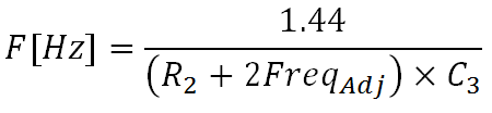
The frequency can be tuned with Freq_Adj potentiometer, instead the power to antenna is controlled using Out_Pwr trimmer. To achieved exactly 7.83Hz a multimeter should be used, also a flashing LED is connected to have a visual check.
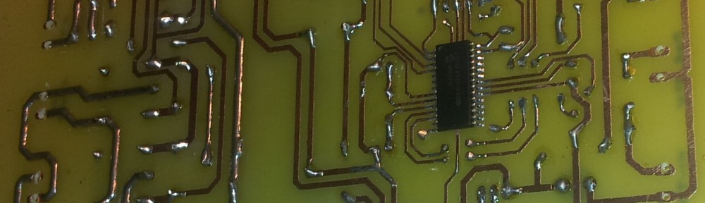
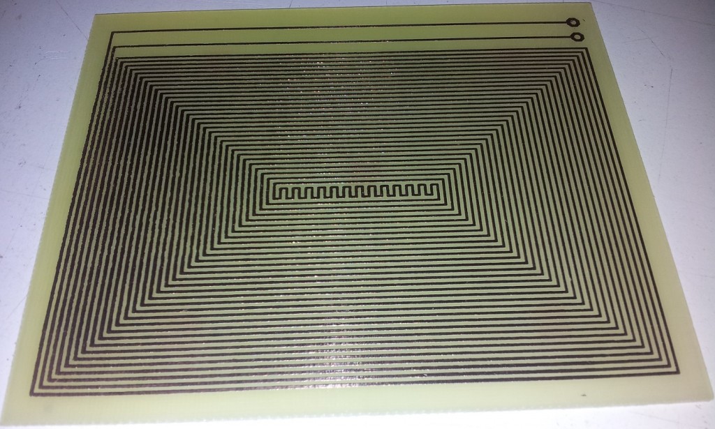
The antenna is printed in a PCB, shown below
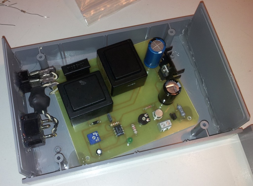
I’ve enclosed the whole circuitry in a plastic box

Ready to print PCB here
Hello,
Can you please post the PCB’s for printing?
Thank you in advance !
PCBs added in the post 🙂
Thanks for the interest
Where ? Don’t see any link.
Alain
It is near the last red words “Ready to print PCB”, click on “here”
I don’t know if the pdf’s were here at my first post, but thank you for the PCB’s.
Hello, what’s the size of the antenna?
Is the PCB scale 1:1?
Thank you
Yes, the scale is exactly 1:1
Hi,
can you email me the complete diy projects guide with parts list and assembly guide.
Thank you
All the material that I’ve made is on the article. For the assembly part, just PCB making and some soldering skills are required
Hello,
Do you have this file in Gerber format.
Thanks
jas
I don’t use Gerber since I’m doing the PCB via toner transfer or UV method
Hi Fabio,
Can you please send me (by email to [email protected]) the PCB layout of the antenne (in PDF) ?
Many thanks !!
Best regards,
David
I’m searching the PDF, I’ll send it to you as soon as possible
Hi Fabio.
I am trying to build your Schumann generator, and as a total electronics newbie I am a little puzzled.
Would you be so kind as to give me the basics as to the transformers?
What are the input and output voltages supposed to be please?
Would this transformer do the job?
http://www.jaycar.co.nz/Power-Products-Electrical/Power-Conversion-%26-Transformation/AC-AC-Transformers/18V-Centre-Tapped-%289V-0-9V%29-PCB-Mount-Transformer-%28TF411756%29-Bargain/p/MF1210
Thanks in advance
Last one didn’t post, waiting for moderator, or did I check the box saying don’t post just join?
Hi Fabio.
I am trying to build your Schumann generator, and as a total electronics newbie I am a little puzzled.
Would you be so kind as to give me the basics as to the transformers?
What are the input and output voltages supposed to be please?
Would this transformer do the job?
http://www.jaycar.co.nz/Power-Products-Electrical/Power-Conversion-%26-Transformation/AC-AC-Transformers/18V-Centre-Tapped-%289V-0-9V%29-PCB-Mount-Transformer-%28TF411756%29-Bargain/p/MF1210
Well, you are totally free to choose the power transformer. Depending on the country you live, check which are the voltage of your main line (120V, 220V, 240V as example). Then, the transformer should outputs less than 15Vac in order to not overload the regulator. Pay attention also to its current rating, I suggest at least 1A to avoid overheating of the transformer. So that, I would not recommend the transformer that you attached.
Thanks Fabio.
Mains power here in New Zealand is 240v
Seems to be two transformers, one positive, one negative.
Am I right in assuming there is a negative and a positive rail as in a audio stereo amplifier?
So the transformer I linked to was correct in that aspect, (centre tapped) but to high a voltage and too low amperage?
Sorry to be impetuous in my questioning, but this is a project I really want to complete.
Don’t worry. For the circuit, I used two transformers because they are from savaged units and are PCB ready. You just need one power source, and a common bridge rectifier in order to use a single transformer. Try to Google for “12v ac dc regulator schematic” and you’ll find examples of working alternatives to my power part of the schumann resonator. Then, you have just to connect ground and +12Vdc to the oscillating part and you’re done!
You are a star.
Thank you Fabio.
Will email you a photo when I am done as I can’t see a way to post photos here.
So lucky to have come across your page and you.
It would be my pleasure. Good luck with the realization, I’ll wait to hear from you!
Hi Fabio, my bits finally arrived, I soldered it all together, assume the led is supposed to flash, but have a solid light.
Is this indicative of a fault in my circuit?
Sadly, yes. The LED should blink at the resonant frequency. Check for bad solderings or short-circuits. I can help if you provide more information.
Hello,
Can send me gerber file or length of Antenna ?
How can we make the same antenna like you
Sorry for the late reply. I no longer have the source files for the Schumann resonator, cause of a hard drive fault, maybe you can use the PDF attached in the post?
Ciao Fabio,
complimenti per il progetto. L’ho realizzato e funziona perfettamente (ho avuto qualche dubbio sul ponticello tra i due trimmer ma … poi ci sono arrivato).
Volevo chiederti, cortesemente, due info:
1) il motivo per cui hai previsto un by-pass del resistore da 100 ohm in uscita antenna
2) se l’antenna che proponi è sostituibile con avvolgimento secondario di un trasformatore o una grossa bobina di filo. La frequenza (7,83 Hz) credo possa concedere ampie possibilità, ma forse ci sono altri motivi?
Grazie comunque (anche per la qualità della documentazione)
Maurizio
Ciao Maurizio, scusami se ti rispondo solo adesso. Il motivo del bypass è poter controllare la potenza erogata in uscita (ed il conseguente sovraccarico del bjt finale). L’avvolgimento lo puoi sostituire tranquillamente. Credo che te abbia già completato il progetto e mi piacerebbe vedere come è venuto!
I ordered 10 antenna PCB’s in china. I have 7 for sale. 17 USD + shipping. Email if you want one:
picomatic at gmail dot com
Thanks but I’m not interested. Can you show us the final assembly of your Schumann Resonator?
Hello,
Thank you for the information.
I have question
How long the distance of frequency cover by antenna ? I mean once it sending frequency how much distance in meter it cover ?
the circuit you give is square wave or sine ?
I have not extensively checked, but I think a room of 10×10 meters is very well covered
Hello,
I also try to did making as per the instruction. But where to place multimeter to check ?